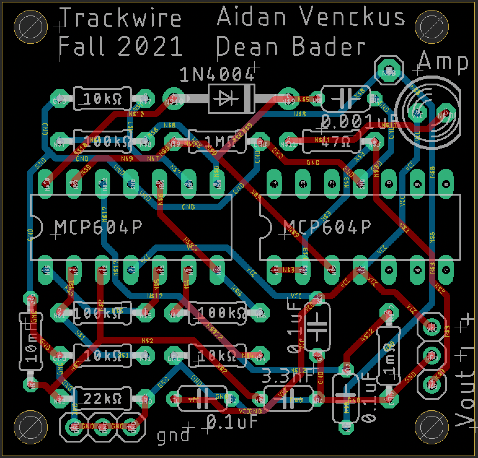
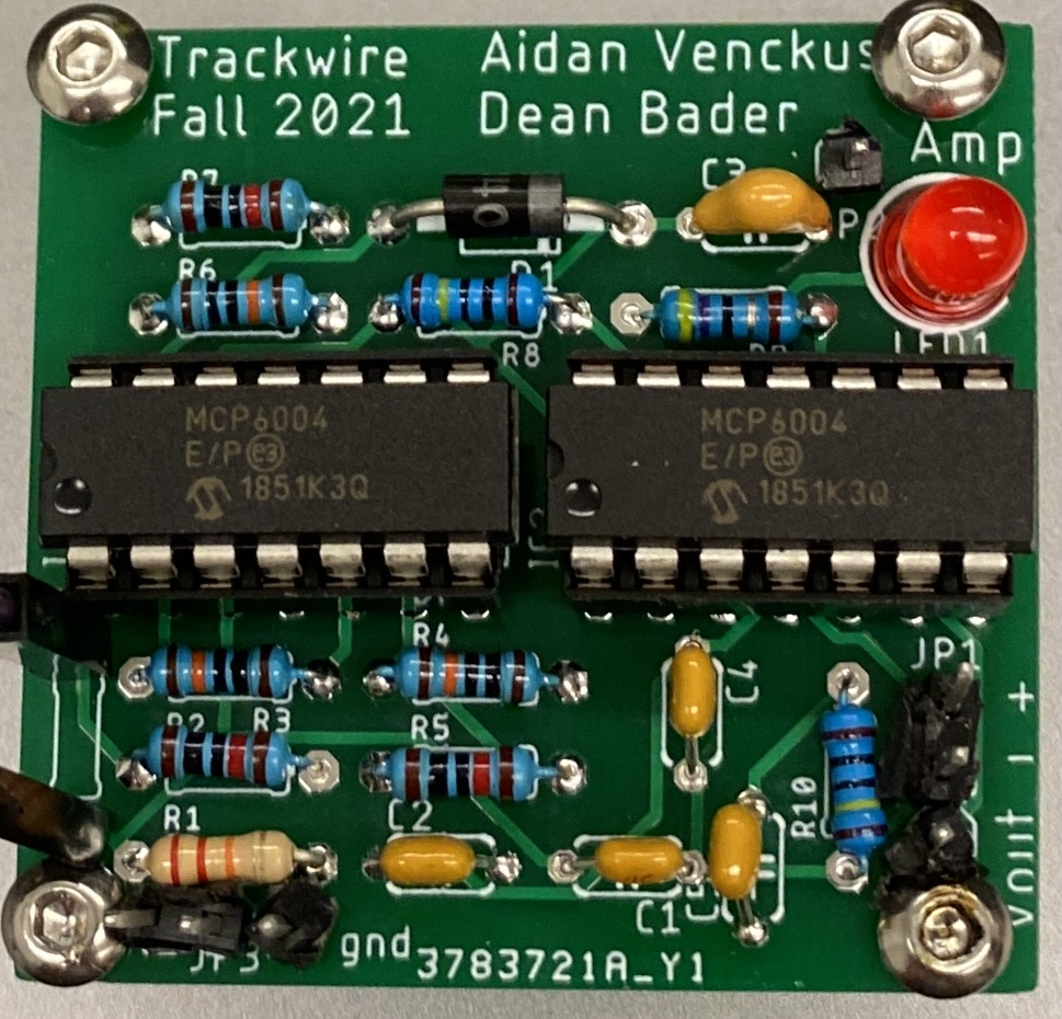
This was a trackwire detector which I used on my capstone autonomous ground robot. It worked based on a inductor that
would try to read the magnetic field of a wire with osilating current running through it, take the signal, amplify it,
then sample the signal through a peak detector and comparator. This allowed the signal to go from analog to a digital
high and low to be read through an LED and in most cases the microcontroller IO.
Trackwire Stages:
Input Stage
- Starts with a a tank circuit which is a resonant oscillator that gets the signal from the track wire through it’s inductor.
The capacitor fills up with charge and it oscillates because the capacitor gives charge to the inductor and then the capacitor flips polarity (this causes a sine wave)
Amplification Stage
- Takes the Input and Amplifies the signal with 3 (11x gain) non-inverting op-amps
Peak Detection Stage
- The signal goes to a peak detector to make sure we have high wave outputs
Comparator and hysterisis Stage
- I took out the comparator for this PCB because I wanted to direcly sample the analog signal through a ADC and be able
to set the comparator and hysterisis values through software
Output Stage
- The signal now gets passed to a buffer and LED to be able to show the resulting output